Note: This site relies heavily on JavaScript to display formulas. Please enable JS to get the full experience.
I tried my best to offer alternatives, if you absolutely can't activate it, but it'll be subpar. You have been warned.
Before we dive deep into the topic and explore how things work together, I added this step by step list for you, to go through, if you just want to "do this", or just need a quick "tl;dr" kind of list to refer to.
Preface
Reference literature collection
While I've been working on a video rebuilding my old, small EL91 valve amplifier that I cobbled together as a 16 year old, I noticed a peculiarity.
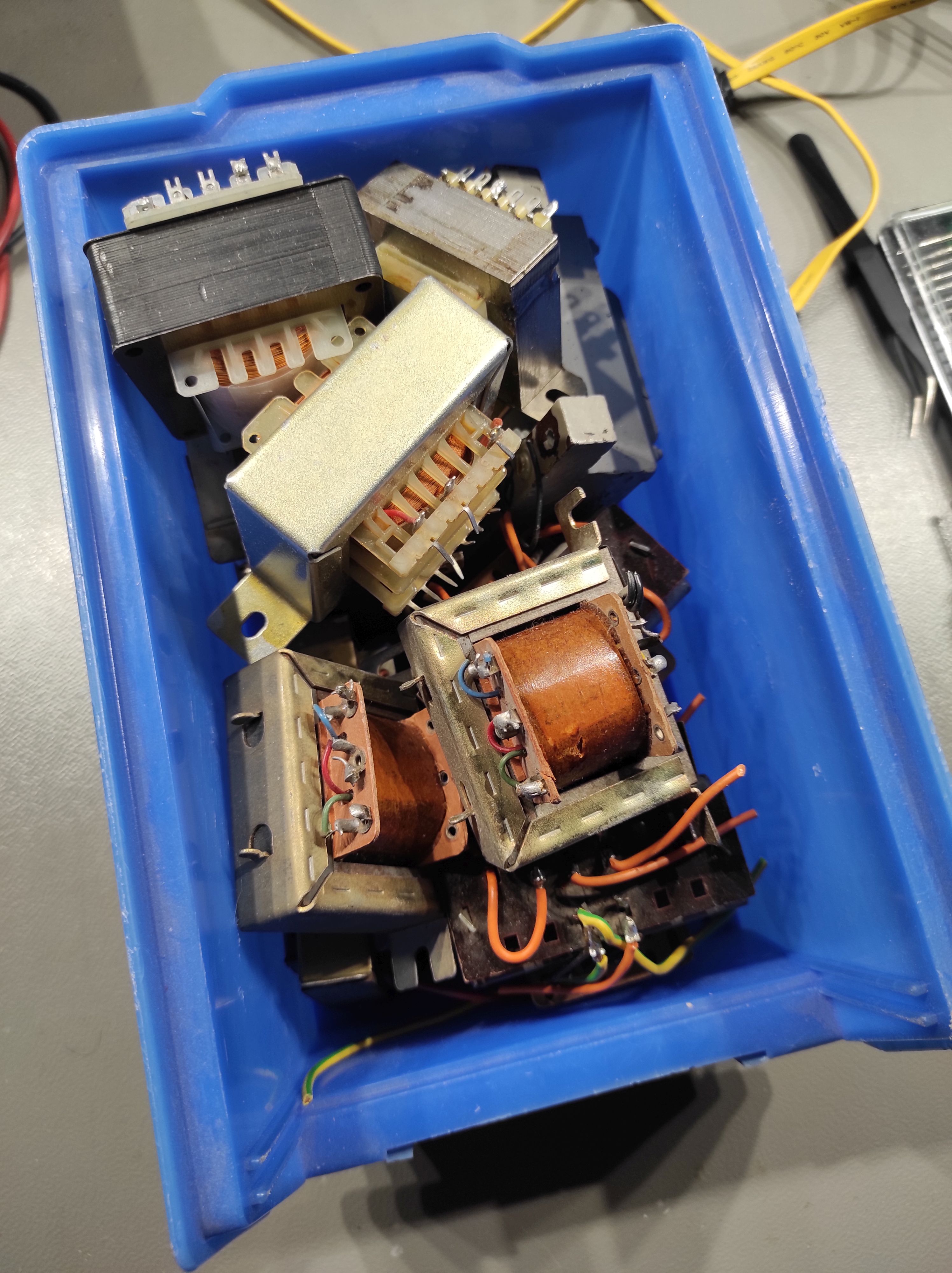
You know, I have a lot of literature about electronics. Quite a lot, actually. The picture to the right is just a quarter of my technical literature.
But in none of the books I have I found a good, beginner-proof, step by step description how to calculate the neccessary values for a Twoob amp,
nor any reference on how to even start with the hobby.
This is part of the reason why I just threw together parts, looked at other schematics and hoped for the best when I built the amp the first time.
I had pretty good success with it, but the circuit was far off from perfect, and it was just pure luck that it worked reliable all these years.
Now I'm much more experienced and understanding even complex formulas is not a problem anymore,
but searching for guides about how to start out as someone who wants to play around with valves resulted surprisingly little good material,
and from experience I know that discussions in forums can also be very tedious and quite offputting.
I want to adress that lack of guidance.
So, how do you begin?
There are two basic ways how you can tackle your first amplifier build.
You either buy everything new and build a known circuit (or calculate it from scratch)
or you can use material you have already flying around.
We want to focus on the later approach, as the first one comes in naturally after you understood the working principles that we want to explore by buying as little new stuff as possible.
Also, as you might have noticed already: I use the term tube or valve or simmilar things how I feel like using them. They are all the same.
Unknown Output Transformers
What you need
To get started building your own beginners tube amplifier you don't really need that much. You need:
A power transformer, fit to your tubes
Audio output transformers with an impedance to fit your tubes and speakers
At least one output- and one small signal tube, or a combination of both, per channel
Some passive components
Now you might happen to have disected an old radio and grabbed parts from there - perfect, thats a good start, we have a working set of components already!
[Don't intentionally destroy nice, old radios, try to find ones that are already very rotten.]
The power transformer provides your amplifier with the power it needs.
A tube circuit usually needs one or more low voltage, high current heater voltages, typical values are 6.3V, 12.6V, 4V and several others at anything from a few ten milliamperes to tens of amperes.
For our project we are likely to be using 6.3V or 12.6V.
Tubes also need a high anode voltage, which is somewhere between 150 to several hundred volts at some low milliamperes.
For our beginners project we probably end up with something around 250V at 50mA or less.
And yes, you can absolutely use more than one transformer, if you don't have one with the fitting voltages.
Using two transformers back to back is also an option.
The output transformer basically keeps your speakers from burning up due to the high DC voltages present at the tubes anodes,
while at the same time transforming the low impedance of your speakers to the high impedance of the tubes, allowing the circuit to function in the first place.
Therefore, the tubes and the output transformers have to match in terms of their impedance and power rating.
You can vary a bit by biasing the tubes a bit different, but we won't go into that detail right now.
Try to use tubes that match the output transformers and vice versa.
We will go into detail what that exactly means a bit further down.
Now if you are not so lucky to have a matching set of output transformers and tubes from just one radio, we first need to find out the exact values of the transformers. So lets see how we tackle that task.
What exactly is an Output Transformer?
Note: You can skip this chapter if you know the working principle behind transformers, or just don't care.
Its ok. I will write an in depth basics article about your standard components, eventually. You can read that one instead.
You might wonder if you can just use a regular power transformer to replace the (usually pricey, if bought new) audio output transformer.
Yes, you can, if you are desperate.
If possible in any way, try to get a real output transformer. The reason for that is simple.
Power transformers are meant to - well, power stuff.
They usually have one or more primary windings and one or more secondary windings, that are just wound straight on top of each other.
Audio transformers on the other hand are designed in a way that they affect the signal the least and just transform the impedances from one station to the other.
They are way more complex, they often have split the primary and secondary into several parts that are alternating, to achieve tightest signal coupling.
Also, power transformers generally don't have an air gap between their laminations, which is crucial in output transformers, as it reduces the risk for the core going into saturation
due to DC biasing of the transformer thanks to the anode current of the power tube.
[That is in single ended amplifiers. Push-Pull topologies are balanced and can work without an air gap.]
So, we can say, an audio transformer is a specialised, more precise, higher quality variant of a power transformer.
Will a power transformer transform audio signals? To a degree, yes.
Will an audio output transformer power stuff? To a degree, yes.
But if you use a standard power transformer, you will will have higher losses, worse performance, worse sound.
And if you use an audio transformer to power things, you are a maniac.
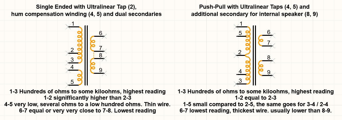
You have to keep in mind that there are potentially more than one taps on an output transformer.
You can identify these easily with a multimeter in resistance mode.
You can also determine which side is the "primary" tube side and which is the
"secondary" speaker side - the speaker side is always the lower ohms one with usually way thicker wire.
Output Transformers can have:
More than one (resistive identical) secondary, or a center tapped secondary
This is usually to use them with either 4 or 8 ohm speakers
If you have that, you are super flexible, as we will see later.
Two non identical secondaries
This is usually to allow connection of an external speaker to a radio having an internal one.
Probably the most tricky one to clearly identify, you should tend towards using
the lower resistance winding with the thickest wire diameter for your secondary.
Hum compensation windings or (rarely) taps
These are wound on the primary side of the transformer
They have a very low inductance and resistance
They are usually a seperate winding, not connected to the primary itself
We ignore these for now. Do not connect anything here. You could, potentially, worsen your signal.
Ultralinear taps
These are taps on the primary, that are off-center.
You measure a clear missbalance of resistance from the tap to both ends.
These can be pretty interesting, but we ignore them for now.
You use the full winding for your anode connection, leaving the tap open.
A center tapped primary
This is most certainly an output transformer for a push-pull configuration.
We can't use this one for our first Amplifier, we need one for single ended circuits (remember the airgap).
Combinations of all of the above.
The most common one is probably the version with an extra ultralinear tap, followed by the standard one primary - one secondary version.
Below I have drawn examples for output transformers sporting all the things mentioned. Click the thumbnail to enlarge it.
Schematic diagram of output transformer options. Click to enlarge.
Now what is impedance?
Note: You can absolutely not skip this chapter. It took me a while to write, so please appreciate it.
Also, you might not understand the following methodology, if you skip this. ;-)
In the previous chapter I briefly mentioned, that an audio transformer is used to match impedances.
The word "impedance" sometimes sends shivers down the spine of people, because its closely related to complex maths.
And hobbyists rarely like calculating with imaginary numbers and solving formulas that have a "j" in them.
Luckily we don't have to bother with that, as we are not interested in phase shifts and other nasty things,
for what we know, the impedance of a transformer is its resistance, just for alternating current.
Therefore, the formula for the impedance of an audio transformer is \(Z = \frac{u}{i}\), and that is just ohms law.
Thats it. No complex maths needed. It doesn't get much harder than that.
But be careful! You can't just take your multimeter and measure the resistance of the transformer.
That would give you its DC resistance, but we need to know the AC resistance = impedance.
So why do I need that?
We know the following: Our speakers have an impedance of around $Z = 4 \Omega$ to $Z = 8 \Omega$.
With such a low impedance it is crucial to provide enough current to drive the speakers appropriately.
If we look at a tube now, we can imagine that pushing electrons through a vacuum is quite resistive,
therefore tubes have a much higher output impedance, usually in the region of kiloohms.
This makes them require way way higher voltages to do any kind of work than a speaker could reasonably survive,
while at the same time they would probably melt their glass envelope, trying to drive the speaker with the current needed.
The output transformer enters the stage.
As it is an transformer, albeit a special one, the standard formulas apply here as well.
We can calculate the winding ratio by counting turns, measuring voltage or measuring current,
since the ratios for a transformer are defined by $ N = \frac{N_1}{N_2} = \frac{U_1}{U_2} = \frac{I_2}{I_1}$.
In this formula we can see, that the current behaves inverted to the voltage, so if the voltage on one winding of the transformer rises, the current on the other winding rises proportionally.
This is exactly what we need - high voltage on one side, high current on the other. Using a transformer we are able to "translate" the impedance of the speaker to the tube, so they both can work together.
Now going back to the beginning of this chapter, knowing the formula for the impedance of a transformer, we can now develop a method to measure and calculate it, using known values.
First we need to know the turns ratio, which we can calculate after measuring the voltages over both windings - the exact procedure will be explained in the next chapter.
$$ \tag{1} N = \frac{U_1}{U_2} = \frac{I_2}{I_1} $$
We can solve formula 1 to U1, U2, I2 and I1:
$$ \tag{2} N = \frac{U_1}{U_2} \iff U_1 = N \cdot U_2 $$
$$ \tag{3} N = \frac{U_1}{U_2} \iff U_2 = \frac{U_1}{N} $$
$$ \tag{4} N = \frac{I_2}{I_1} \iff I_1 = \frac{I_2}{N} $$
$$ \tag{5} N = \frac{I_2}{I_1} \iff I_2 = N \cdot I_1 $$
Using Ohms law (applied to the impedance on one side n of the transformer) we know:
$$ \tag{6} Z_n = \frac{U_n}{I_n} $$
We now can express the impedance on one side in relation to the the impedance on the other side, combined with the turns ratio. We solve:
$$ \tag{2 and 4 in 6} Z_1 = \frac{U_1}{I_1} \iff Z_1 = \frac{N \cdot U_2}{\frac{I_2}{N}} \iff Z_1 = Z_2 \cdot N^{2} $$
As well as:
$$ \tag{3 and 5 in 6} Z_2 = \frac{U_2}{I_2} \iff Z_2 = \frac{\frac{U_1}{N}}{N \cdot I_1} \iff Z_2 = \frac{Z_1}{N^{2}} $$
Also, if you want to check your calculation, you can solve to formula 7, and see if you receive your calculated turns ratio, if you put in your impedances.
$$ \tag{7} N = \sqrt{\frac{Z_1}{Z_2}} $$
So far pretty easy, isnt it? It all boils down to a simple division or multiplikation.
We know the impedance of our speaker, so all we need now to correctly calculate the primary impedance of the output transformer is the turns ratio. So lets see how we can measure and calculate that.
How to measure impedance [of an audio output transformer]?
Measuring impedance directly is not easy to do, as we can't just take our multimeter, switch it to an impedance mode, and measure it.
To do that, we would have to open up a big can of worms and grab some special equipment which hobbyists usually don't neccessarily have at hand.
Therefore we go for the method of calculating the "primary" impedance by knowing the "secondary" impedance (which is the speaker) and the turns ratio, as discussed above.
The first and the only thing we have to do, besides calculating things, is to feed a known signal into the speaker side of the output transformer
(which is the one with the smallest ohmic resistance), and measure what comes out of the other side.
Keep in mind that Output transformers CAN have more than one tap on both primary and secondary,
how to know wich exact one you need to look at is written in the chapter "What exactly is an output transformer?".
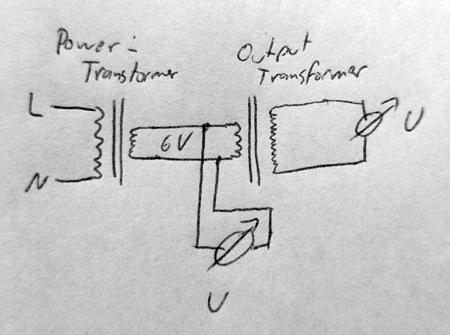
Measurement setup, Variant 1
Now there are several ways to do this. The most common one I saw while researching for this article, was to just use a standard low voltage power transformer to feed for example 6V AC at 50Hz into the output transformer.
This totally works, if you don't have other options, but I suggest to go a tiny extra mile and use variant two, we will explore why later.
The schematic for this setup is super simple, and you can see it down below. One low voltage transformer and two (or even one would work) voltmeters capable of measuring 50Hz AC is enough.
Of course you can also use a scope to measure the levels of your signals, which also allows you to see at a glance if something might become fishy (eg., if your waveforms start to look very different, besides the difference in level).
So, all you have to do is to apply the low voltage to the secondary of the output transformer, measure the voltage going in and the voltage going out, and thats it. Can be done in a few seconds.
Measurement setup 1, simple version
Measurement setup, Variant 2
However, I suggest the second variant, which gives a bit better results. It is just a slight bit more work, but most hobbyists might already have the needed components at hand.
What we do here is replacing the simple mains power transformer with a signal generator and a little AF amplifier.
If your signal generator is capable of delivering enough power to drive a low impedance inductive load you can even skip the amplifier.
The schematic for this setup is not very complex either, and once again, you can see it down below.
Measurement setup 2, more advanced version
You might have noticed the resistor in parallel to the output of this circuit.
This is to calm down potential resonance effects created by parasitic capacitances and inductances,
resulting in self resonating at higher frequencies that COULD potentially cause harm to the transformer, or yourself.
Choose a value around 1 to 10 kiloohms.
So why should we choose this method? The reason is pretty simple. A transformer has a characteristic curve,
with a reasonably flat middle part between roughly 100Hz and up to around 10 to 20kHz, and a dip towards the very low and very high frequencies.
A good example of such a characteristic can be seen for example at Röhrentechnik.de.
In the lower frequency range that is a result of the primary inductance limiting the signal level.
$ Z = \frac{1}{2 \pi f L_P} $ shows that the impedance rises at lower frequencies, also, the inductance usually has a slight drop in the lower and higher ranges as well, so these effects stack up.
This can only be conquered by having a transformer with more turns on its winding, which is also the reason why bigger output transformers often have a better frequency response.
In the higher frequency range we have basically the opposite effect, more turns on the winding increase
the leakage inductance and inter-winding-capacitances, which create a LC resonance circuit with a resonance frequency of $ f = \frac{Z}{2 \pi L_l} $, which can result in a dip or a peak in higher frequencies.
This means, that an output transformer is a balance act between good low and high frequency performance, which requires good knowledge to be able to make a product that performs well.
If we look again at the example characteristics, we can see that the mains frequency with its 50Hz is still a bit in the non linear section of the curve.
Taken into account that this output transformer is made by a company that specialised in tube output transformers for quite some years, we can assume that most transformers
that we rip out of old rotten radios or find at swap meets probably don't reach that kind of performance, and are way worse in terms of frequency response.
Therefore, in my humble oppinion, it is a good idea to be able to measure outside of the non-linear frequency range, and choose a measurement frequency
of for example 1kHz, which is also a standard frequency often used in performance data of amplifiers. You can also use this method to sketch your own frequency response graphs,
albeit a crude one, as we miss the dc premagnetisation current from the tubes anode, which has a noticable effect on the performance as well.
I suggest to take three data points, for example at 100Hz, 1kHz, 10kHz, to have a way of creating a rough estimate of a sort of average value to calculate our turns ratio and with that the impedance.
Lets get calculating!
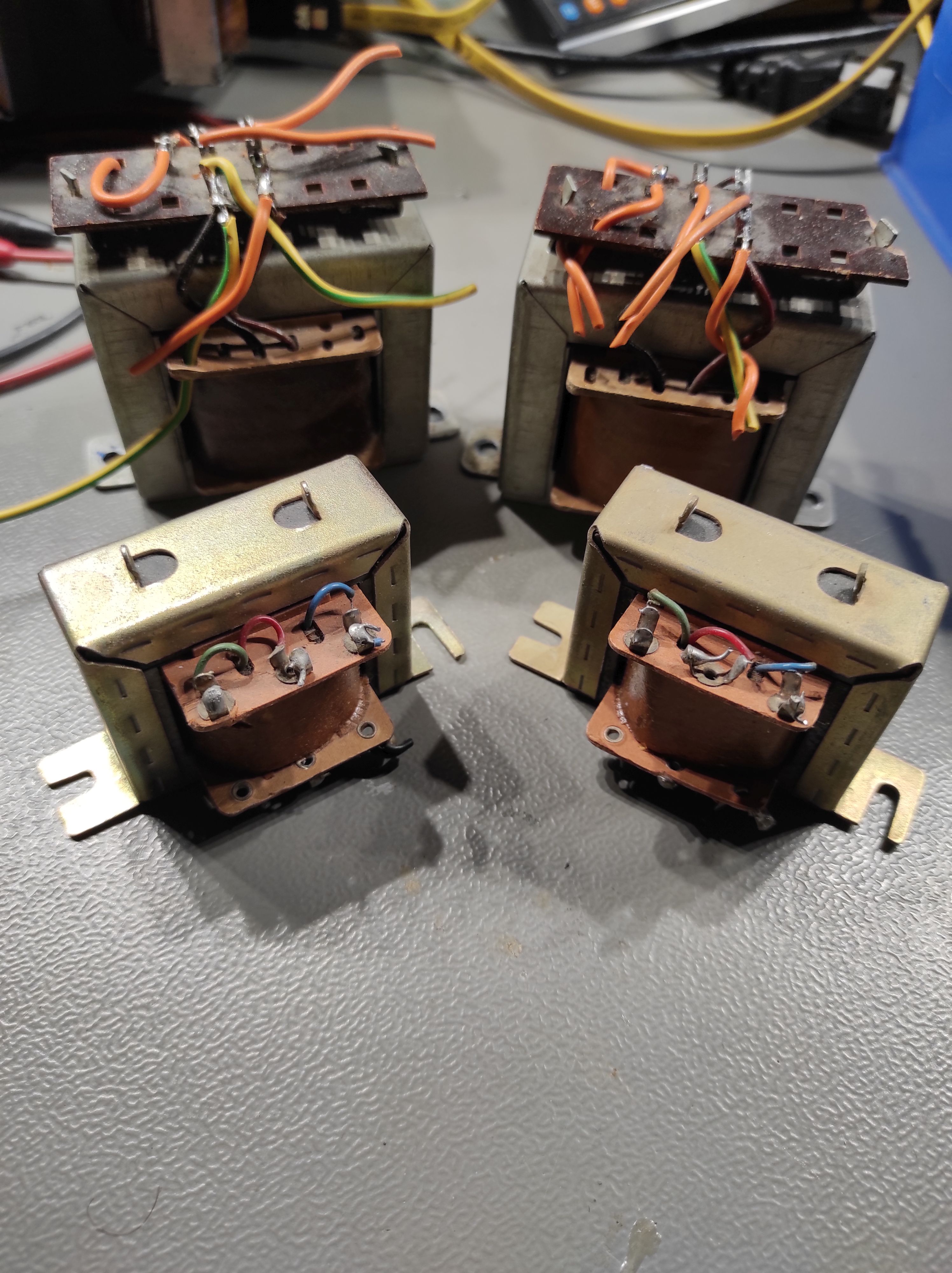
2x 2 similar yet very
different Output Transformers.
Now that you have decided for a measurement setup, measured your primary and secondary voltages, you came up with a result that looks something like the following tables.
As an example I measured three pairs of output transformers:
The tiny ones from my "tinyamp" that I measured in the youtube video below
These are your standard SE transformers, but they have a seperate winding, probably a shield winding, as its not connected to anything
The two smaller (but still bigger than the tiny) ones in the pic to the right
These Transformers have an extra secondary winding for an internal speaker
They also have an ultralinear tap
The two big (but still pretty small) ones in the pic to the right
They only have an ultralinear tap as a "special feature"
I took a measurement at 50Hz, 100Hz, 1kHz, 10kHz, 20kHz and 30kHz, to show some interesting effects.
To account for measurement inaccuracies I repeated every measurement three times and took,
when there are no outliners, the average of all three samples.
In the table you see the values I measured in the scheme of "Input Voltage [mV] | Output Voltage [V]". We will calculate the turns ratios from that in the next step.
Measurement Results
Sample
Voltages at measurement frequency
50Hz
100Hz
1kHz
10kHz
20kHz
30kHz
Tiny A
252 | 10.4
468 | 20.2
460 | 20.2
612 | 29.6
328 | 19.4
140 | 13.6
Tiny B
488 | 20.6
476 | 20.4
504 | 22.0
568 | 27.4
268 | 16.8
96 | 11.2
Medium A
512 | 23.8
496 | 23.4
540 | 25.8
556 | 29.6
260 | 18.8
76 | 13.2
Medium B
440 | 19.8
428 | 19.8
472 | 22.6
540 | 29
236 | 17.8
68 | 12.4
Large A
772 | 20.2
792 | 20.8
832 | 21.8
672 | 20.8
264 | 14.4
176 | 10.6
Large B
720 | 18.8
1380 | 35.6
720 | 18.8
600 | 18.0
780 | 43.6
440 | 31.2
if you have a keen eye, you can already see that there is a significant difference for all of these on the upper range, and a slightly smaller one towards the lows.
Lets see if our eyes betray us, and calculate the turns ratio, using formula 1 from above.
Lets calculate some impedances (and turn ratios)
Lets make an example here and take the measurement for 1kHz for the medium size transformer A. We measured 540mV going in, and 22.0V coming out.
With formula 1 we know that $ N = \frac{U1}{U2} = \frac{25.8V}{0.54V} = 47.\overline{7} $.
Again, not that hard, is it? We have just calculated the turns ratio. Lets repeat that for alle the values, rounding to one digit.
Calculated Turns Ratios
Sample
Calculated turns ratio at measurement frequency
50Hz
100Hz
1kHz
10kHz
20kHz
30kHz
Tiny A
41.3
43.2
43.9
48.4
59.1
97.1
Tiny B
42.2
42.9
43.7
48.2
62.7
116.7
Medium A
46.5
47.2
47.8
53.2
72.3
173.7
Medium B
45
46.3
47.9
53.7
75.4
182.4
Large A
26.2
26.3
26.2
31
54.5
60.2
Large B
26.1
25.8
26.1
30
55.9
70.9
And indeed, we see a quite substantial difference going to the treble region, and a lower one around the bass region.
We can also see, that the bigger transformer has almost no problem with the bassy region, and it is also not too bad in the treble region,
while the medium ones are actually worse than the tiny ones. Interestingly enough, the medium ones are also the most modern ones. Go figure.
Now, for the next step, we want to calculate the impedance. To do that, we utilize the impedance formula in the formula box above.
As we want to know the impedance on the primary side, we utilize $ Z_1 = Z_2 \cdot N^2 $, and we assume a speaker impedance of $ 8 \Omega $ for our calculations.
You should absolutely try to know the impedance of your speakers beforehand, as the speaker impedance affects the primary impedance directly.
Imagine you calculate with an assumed $8 \Omega $ speaker, than you use a $ 4 \Omega $ speaker instead, and suddenly your poor output tube only sees half the impedance.
That would signifficantly affect the performance. If you need to be somewhat universal, calculate with 6 ohms, but than you are always off. Ideally you would have a transformer with split secondaries.
Now, lets calculate!
Calculated Impedances
Sample
Calculated impedances at measurement frequency
50Hz
100Hz
1kHz
10kHz
20kHz
30kHz
Tiny A
13.6$ k \Omega $
14.9$ k \Omega $
15.4$ k \Omega $
18.7$ k \Omega $
28.0$ k \Omega $
75.5$ k \Omega $
Tiny B
14.3$ k \Omega $
14.7$ k \Omega $
15.2$ k \Omega $
18.6$ k \Omega $
31.4$ k \Omega $
108$ k \Omega $
Medium A
17.3$ k \Omega $
17.8$ k \Omega $
18.3$ k \Omega $
22.7$ k \Omega $
41.8$ k \Omega $
241$ k \Omega $
Medium B
16.2$ k \Omega $
17.1$ k \Omega $
18.3$ k \Omega $
23.1$ k \Omega $
45.5$ k \Omega $
266$ k \Omega $
Large A
5.48$ k \Omega $
5.52$ k \Omega $
5.49$ k \Omega $
7.66$ k \Omega $
2.38$ k \Omega $
2.90$ k \Omega $
Large B
5.45$ k \Omega $
5.32$ k \Omega $
5.45$ k \Omega $
7.20$ k \Omega $
2.50$ k \Omega $
4.02$ k \Omega $
So we see, if we choose an 8 ohm speaker, we could use the tiny transformers for tubes that expect a 15$ k \Omega$ transformer,
the medium ones for 18k, and the big ones for 5.5$ k \Omega$.
This fits pretty good, knowing that the big ones were used in an EL84 amp that works with around 5.5$ k \Omega$.
For the other two we have to think a little. Speakers in old radios were often around 6$ \Omega$ in impedance, so lets see what would happen if we calculate with four and six ohms instead.
I know that the tiny transformers were used with EL95 tubes, which expect an impedance of around 8$ k \Omega$, which fits perfectly on four 4$\Omega$.
I have no idea what the medium ones were for, these are new, unused, were not in a radio before. But one could probably make them work with something like a 6V6GT, which can work with around 9$ k \Omega$.
And there we have it. Figuring out what audio output transformers we have in our hand is not that hard, even though it looks intriguing at the beginning.
Step By Step
Measurement Part
Step 1: Inject known or measured low AC voltage into secondary.
Step 2: Measure voltage on both sides and write them down.
Calculation Part
Step 3: Calculate turns ratio.
$$ N = \frac{N_1}{N_2} = \frac{U_1}{U_2} $$
Step 4: Calculate impedance with turns ratio and known speaker impedance.
$$ Z_1 = Z_2 \cdot N^2 $$
Where:
\( N \): Winding ratio
\( N_1, N_2 \): Number of turns
\( U_1, U_2 \): Voltage over winding
\( Z_1, Z_2 \): Impedance of winding
About measurement techniques
One could argue, that my prefered method of using a 1kHz Signal is not really better than using a 50Hz transformer, compared to the huge differences from 10kHz onwards.
Lets take a look at that.
Lets take the best of the six tested transformers as an example, one of the large ones. The difference between 50Hz, 100Hz and 1kHz is basically zero, so yes, for that case, it would not make any difference.
But what about the other ones? Lets take the tinys, as we don't want to use the worst (but for my argument best) example, Tiny B to be precise, to choose the better of the two.
Here we have a difference of $ \Delta N = 0.7 $ going from 50 to 100Hz and $ \Delta N = 0.8 $ going from 100Hz to 1kHz.
Thats also basically the same, isn't it? Well, yes, as long as you don't take the step size into account. We change 0.7 in 50Hz for the one, and 0.8 over 900Hz for the other.
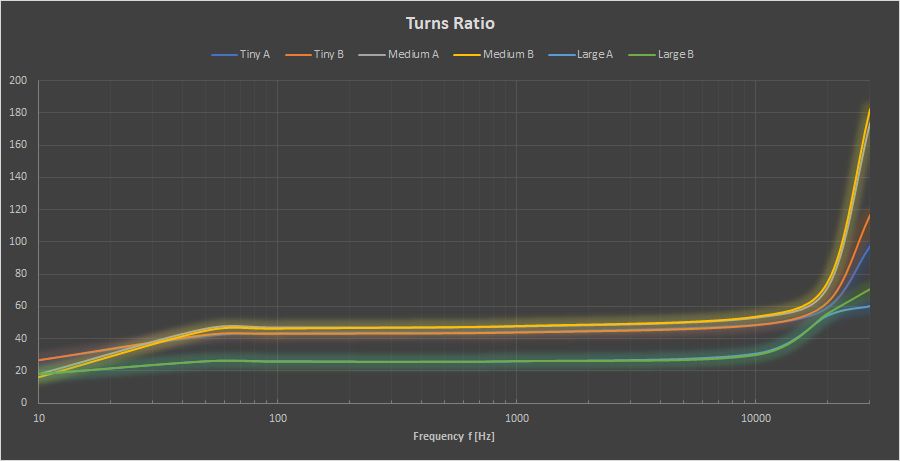
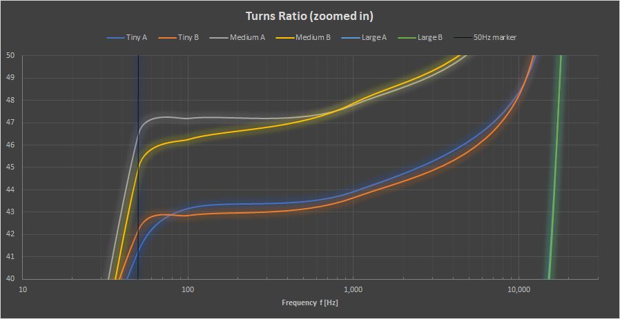
The change of perceived turns ratio and therefore calculated impedance is 18 times stronger in the 50Hz region. If we plot these values, we can see that pretty clearly, at least if we zoom into the interesting part.
But first, lets take a look at the general situation. Please note, that the values under 50Hz are at this point extrapolated values, calculated from the slope of the previous values.
All measured transformers.
And now lets take a look at the zoomed in view. I cropped the chart to only show a ratio between 40 and 50, therefore we can see the curvature better, as it doesn't get smushed by the insane values in the high frequency region.
I also added a marker at the 50Hz position. We can clearly see that we are way off from the linear region with 50Hz mains frequency. People with 60Hz mains are luckier, but still, thats quite a bit off.
The four smaller transformers, zoomed in.
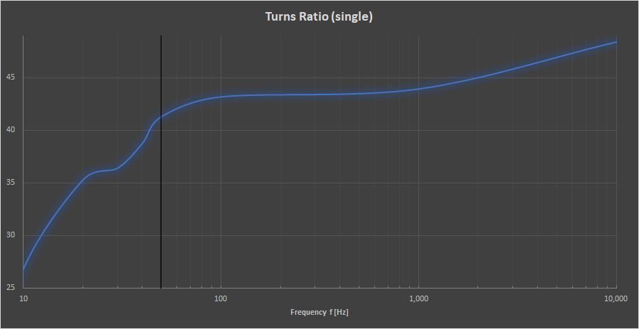
Just for fun I measured a single transformer down to the minimum that my frequency generator would allow for, which resulted in this interesting scene.
I think we can agree that we should try to avoid the low frequency region for our purposes.
Just "Tiny A". And a marker.
Finally, if you want to see a video about the whole process, feel free to watch the one below.